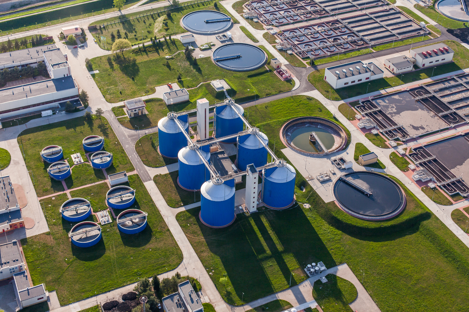
The PVA Treatment Plant is composed by Anaerobic system, and a biofilter, in order to obtain a waste water suitable to be treated in the biological plant.
1.1 Biofilters
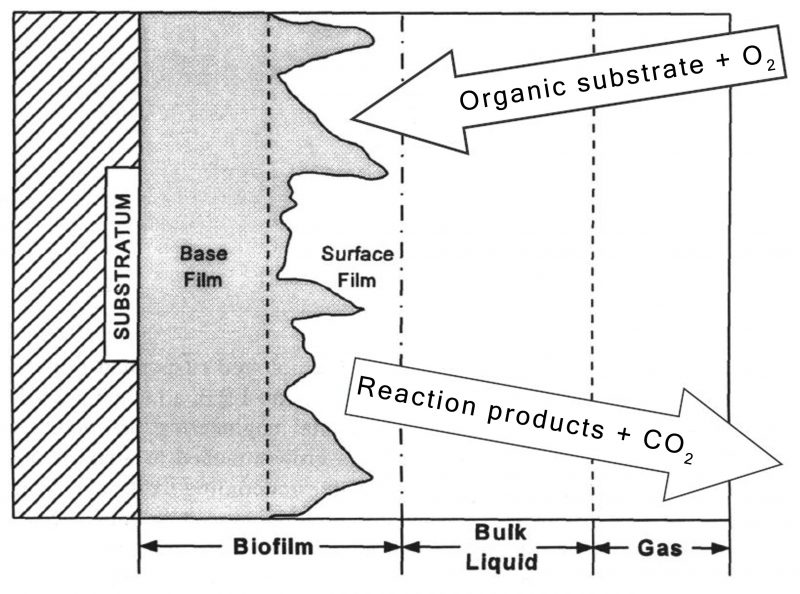
The biological oxidation is the “core ” of the plant. The functioning principle is based on the utilisation of aerobic bacteria colonies, naturally present in water to be treated. These bacteria have three fundamental characteristics:
- they accomplish their vital cycle metabolising the organic matter
- they reproduce increase quickly.
- they tend to live in and to form colonies
To assimilate and to transform organic matter, the bacteria need oxygen. The final products of this process are H2O, CO2 and new living substance. The oxygen source will be partly that existing in the water and partly that supplied from outside. In that way the natural bio-degradation accelerates, reducing the time of the process, which otherwise should be longer and thus unacceptable. The oxygen feed causes a very fast multiplication of the bacteria and then the growth of colonies.
In these ones protoplasm cells, coming from organic synthesis, organic metabolised solids and residual organic matter are concentrated. Moreover, through adsorption mechanisms, also organic and inorganic non separable solids tend to bond to the biofilm.
Bond biomass systems (biofilters) further the growth of bacteria colonies on a substrate made of a bed of filler material, suitably shaped in order to guarantee the higher possible surface extension, reducing at the same time taken up volumes.
Compared to an oxidation process with activated sludge, in biofilters we can reach an higher variety of bacteria population, with consequent physiological stratification of the biofilm. For some steps, this fact make the biological degradation process in bond biomass filters faster the what append in active sludge tanks.
The supply of oxygen, necessary for the growth of bacteria colonies, is guaranteed by “air lift” systems, that can create into the liquid optimal currents and agitation for an efficient performance of the process.
Then, main advantages of biofilters are:
- the possibility to free the cellular residence time by the hydraulic retention time;
- the possibility to increase the biomass concentration, even up to 40 gr/lt;
- the reduction of reactors volume and taken up surfaces, also thanks to modular construction;
- the improvement of performance and then the possibility to reach more restrictive standards at discharge;
- the independence of the process from the settleability characteristics of sludge;
- low energy consumption;
- easy management with few maintenance requirements;
- better properties on sludge thickening, that make not necessary a secondary sedimentation process;
- sludge recirculation is not necessary;
- high variety in bacteria population and then, better recovery from toxic shocks, fast adaptation to load change and versatility on application.
1.2 Microbiology and biochemistry anaerobic technology
Experience: We are proud to inform you that we have already a running pilot system, with the size of the real needs. It is working in Welspun factory, for the remuval of the PVA, and the results are positive, and the customer is satisfyed.
Introduction
Anaerobic treatment of waste water is a biological method which is characterized by the production of methane (CH4). The active microorganisms all belong to the group of anaerobic bacteria, i.e. bacteria which are able to and in most cases can only exist in an environment which excludes oxygen. In this context, methanogenic bacteria are in a key position.
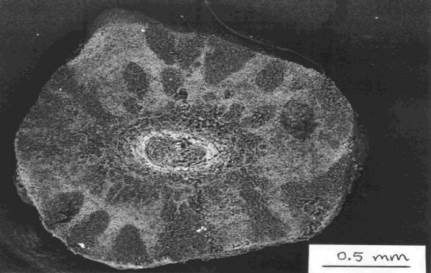
The anaerobic degradation process of organic material occurs stepwise (Figure 12).
Four steps can be distinguished:
– Hydrolysis
– Acidification
– Acetogenesis
– Methanogenesis
Normally, each step is carried out by a different bacterial population. The reaction products of one population are the substrates (food) for the next.
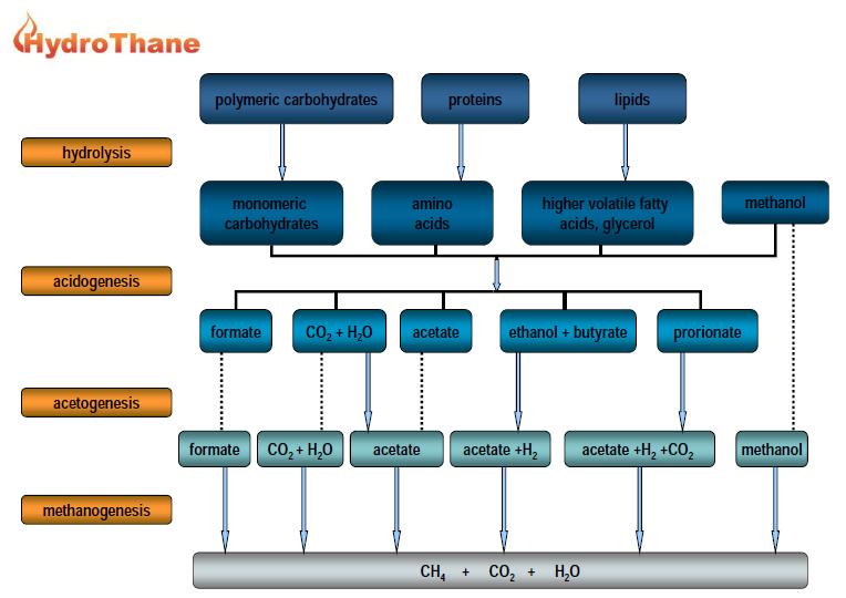
Hydrolysis and Acidification
The anaerobic degradation starts with the hydrolysis of large organic molecules (polymers) like proteins and polysaccharides (starch) which are hydrolysed by exoenzymes. Monomers are formed which are degradable for acidifying bacteria (second step). The monomers are glucose, hexoses, pentoses (sugars) amino acids, alcohol’s and others. In the second step, higher organic volatile acids like propionate, butyrate and others are formed besides acetate. One possible acidification reaction is the acidification of glucose to acetate:
C6H12O6 -> 3 C2H4O2– + 3 H+ – 311 kJ (1)
Glucose can also be acidified under simultaneous production of hydrogen:
C6H12O6 + 4H2O -> 2 C2H4O2–+2 HCO3– + 4 H+ + 4 H2 – 206 kJ (2)
Note that in this reaction HCO3– is produced.
Reaction (1) and (2) show, that the COD-content of glucose is converted in the COD-content of acidic acid. Since no reduced molecules of carbon are released in the gas phase, the COD of waste water does not change and no „purification“ takes place to that point.
Acetic Acid Producing Bacteria (Acetogenesis)
Higher organic acids are transformed to acetate by acetogenic bacteria (third step). However, in some cases the energy output of these conversions is not sufficient to run the reaction. For instance in the conversion of propionic acid:
C3H5O2– + 3 H2O -> C2H3O2– + HCO3– + H+ + 3 H2 + 76 kJ (3)
the change in free energy is positive. According to thermodynamic laws, a reaction only takes place when the change in free energy is negative. This only can happen in reaction (3) when the (partial) pressure of H2 is lower than 10-3 – 10-4 bar.
By a direct consumption of H2 the partial pressure will be kept low and the propionic acid is converted into acetic acid. If this is not the case, propionate will accumulate in the culture which can lead to problems.
Methane Producing Bacteria (Methanogenesis)
The methanogens belong to a special group of bacteria, the archae-bacteria. They are terminal members of the anaerobic food chain, whose metabolic activity prevents the sequestering of large amounts of organic material in anaerobic ecosystems.
The three above mentioned groups of bacteria finally produce acetic acid and hydrogen. Surplus hydrogen can be used by most of the methanogenic bacteria to convert HCO3– to methane according to:
4H2 + HCO3– + H+ -> CH4 + 3 H2O – 135,6 kJ (4)
(Methanogenesis I, figure 10)
The accumulation of propionic acid can be avoided if methanogens and acetogenic bacteria are associated very closely (symbiosis). Than the H2 produced by acetogenic bacteria can be consumed by methanogens and converted to CH4. This is called interspecies hydrogen transfer and takes according to:
C3H5O2– + H2 -> CH4 + C2H3O2– – 26 kJ (5)
Now, the equilibrium of the above reaction is on the right hand side and CH4 is produced by the methane bacteria . The COD in the water will decrease when the gas becomes free. One of the most important steps is the next, which only can be carried out by two methanogens, Methanothrix soehngenii and Methanosarcina subspecies:
C2H3O2– + H2O -> CH4 + CO2 +OH– – 62 kJ (6)
(Methanogenesis II, figure 12)
In this reaction acetate is converted into biogas. This reaction is responsible for about 70% of the biogas produced in anaerobic processes. Here again the COD is removed from the water with the methane.
1.3 Technology of choice
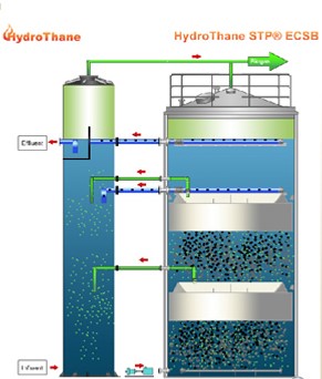
The proposed anaerobic wastewater treatment process (see attached Process Flow Diagram and Mass Balance) is based on the STP ECSB (External Circulation Sludge Bed) process. In the following chapters the different process steps will be described in a general way.
Pre-treatment/pre-acidification Buffer tank
The waste water stream from the production will be screened (1 mm) before it enters in pre-acidification/ buffer tank – of approx. 100 m3 volume.
Buffer – pre-acidification tank should be equipped with mixer and with pH (dosing NaOH), temperature & level measurement. Flow and load are equalized to a preset volume of m3/hr (max.) and max. load of wheight of kg COD/day within the buffer tank which will then be forwarded to the Neutralization Tank.
Neutralisation Tank (NT)
From the pre-treatment the raw waste water is pumped to the Neutralisation Tank. In the Neutralisation Tank the raw feed of wastewater is mixed with recycled, treated anaerobic effluent.
A mixing and measuring loop is fitted as standard to the Neutralisation Tank. In this loop the pH and temperature are measured for process control. As a safeguard against measuring errors due to no flow conditions the measuring loop is equipped with a flow detection switch. To prevent dry running of the mixing pumps level switch protection is installed in the NT.
Alkaline or acid dosing could be required for pH control in the NT, an antifoam dosing connection point is also provided as backup safety.
Biogas produced in the STP ECSB reactor is collected from both the lower section and the upper section of the reactor and is passed through the NT contents thereby stripping CO2 from the biogas into the NT contents. Because of this CO2 removal caustic dosing costs for the process neutralization are minimized.
To create the optimal growth conditions for the anaerobic biomass in the ECSB reactor, required nutrients like f.e. N, P, Micro nutrients, FeCl3, etc. may need to be dosed into the Neutralisation Tank.
STP ECSB reactor
The conditioned wastewater is pumped to the STP ECSB reactor. In this reactor the bacterial conversion process takes place. The biomass in a STP reactor is present in a granular form.
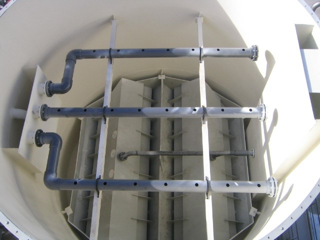
The wastewater enters from below by means of the Distribution System (DS) and leaves the ECSB reactor at the top, after passing two layers of phase-separators (biogas/biomass). The specially designed DS assures an equal distribution of the influent and prevents “channelling” through or “dead zones” in the STP ECSB reactor. The influent waste water passes through a dense anaerobic granular biomass bed where the biological conversion processes take place (see chapter 5.1).
Both phase-separators layers are covering the whole surface of the reactors (see figures 14 and 15). The first separator layer is installed at approx. 14 metre height, creating a high hydraulic and biogas-velocity, loaded reaction-volume below the separator.
The second separator layer is installed approx. 3 metres below the reactor discharge level, in between the separation layers a conservatively loaded, post-treatment polishing step is created. The separators are designed and installed in such way that optimal biomass retention is achieved and maximum capacity and process operation and stability is guaranteed.
The lower part (1) of the reactor contains a highly concentrated expanded sludge bed. The expansion of this sludge bed is created by the upward flow of the influent, anaerobically treated recycle stream and the produced biogas. The effective contact between the waste water and the biomass results in high sludge activity, making high organic loading and conversion rates possible. The first level phase separators also separate the majority of the biomass from the effluent and collects biogas at this stage.
The upper part (2) of the reactor (above the 1st phase separator) is where an effective post treatment and further biomass retention take place. Due to the fact that most COD removal takes place in the lower part of the reactor, the turbulence created by the produced biogas (< 10%) in the upper part is relatively low.
The anaerobically treated water leaves the reactor by means of the effluent discharge piping in the top of the HydroThane reactor. The anaerobically treated recycle stream, to be passed back to the NT, is taken from just above the 2nd phase-separator layer. In this way the final anaerobically treated effluent is discharged under an as low as possible hydraulic velocity, thereby producing optimum conditions for biomass retention, process stability AND the best possible effluent discharge quality.
Sludge concentration in the upper part (2) of the reactor is low, so this means that there is space available for extra expansion of the sludge bed. This will avoid biomass loss during peak loads.
The new HydroThane STP separator is covering the whole surface area of the reactor this means that due to the larger settler surface the reactor can be designed more slender than other EGSB processes. (smaller footprint, see chapter 5.4)
All the biogas collected in the phase separators from both levels in the reactor is piped towards the Neutralisation tank to be used as CO2 stripping gas.
The collected biogas passes through the contents of the NT and into the headspace of the Neutralisation Tank. The Neutralisation tank and STP ECSB reactor headspaces are connected, the overall process operates under biogas pressure. This pressurised design assures a completely closed process and prevents any external odours and emissions. (See chapter 5.4)
The anaerobically treated wastewater and the recycle stream return to the neutralisation tank. The anaerobic effluent discharges under gravity via the internal degasser section of the NT to the sewer or post treatment. The rest of the treated water from the reactor is automatically recycled into the NT and mixed with raw waste water feed.
Manual sampling connections are fitted inside the reactor to allow biomass sampling, inventory and profile monitoring to take place. Based on the biomass inventory and design load, surplus biomass should be extracted. A discharge nozzle in the lower part of the reactor is fitted to extract surplus biomass to the anaerobic biomass storage tank.
1.4 Post Treatment
Depending on the local discharge limits, further treatment may be needed.This has not been allowed for in this proposal.The anaerobic effluent values (5) are shown in the Process Flow Diagram & Mass Balance, these values can be taken as design values for any post treatment required.
Biogas system
All biogas produced by the STP ECSB process can be burned in the biogas emergency burner or can be used for renewable “green” energy production.
The biogas emergency burner is equipped with a pressure control valve which controls the operating pressure in the ECSB reactors and the Neutralisation Tank.
The biogas may also be used in boilers for steam power generation, or in a gas generator or CHP unit for electricity generation. The viability of these options depend on the quantity of biogas produced and the needs of the end-user.
In certain applications biogas treatment is required to assure sufficiently low H2S in the biogas to meet requirements for boilers/gas engine and/or production site permits or SO2 emission limitations.
STP can offer biogas treatment systems on request. For this moment we have not included this in this proposal.
Characteristics STP ECSB process
The ECSB design from STP offers maximum process control because of its fully controlled hydraulic mixing/blending by means of external (re-)circulation pumping. This in comparison with certain systems that have an Internal Circulation that is depending of non “human” controlled parameters or uncertainties like COD loading / biogas production, wastewater composition/biodegradability and last but not least the microbiological activity of available biomass.
The STP ECSB process guarantees you of the best final effluent quality, the treated effluent is discharged with substantial lower hydraulic loading velocities than with any other high loaded anaerobic treatment process available on the market.
The two layer separation design creates maximal process stability and capacity. In the high loaded bottom section main degradation reactions and biogas production takes place, followed by a conservative, low loaded, post treatment polishing step in the middle section of the reactor. The settling area in the top of the process is especially designed for optimal granular biomass selection & retention and best possible effluent discharge quality.
Due to the complete over-pressure design and fixed biogas volumes underneath the water levels of the STP ECSB process a (bio)gasholder is not required!
The over-pressurised and completely closed design prevents air/oxygen entrance. Corrosion is therefore not possible in the STP ECSB reactor. Additionally the STP ECSB design guarantees you of maximal operating and personal/employee safety! A minimum of biogas equipment installed and NO leakages/emissions of potential dangerous biogas possible!
The pressurised STP ECSB design excludes all odour or smell nuisance and/or emissions. All potential “sensitive” emission spots as normally available by “atmospheric anaerobic treatment processes are fully integrated into the pressurised & closed biogas circuit. There is no need to install external sensitive odour/smell removal equipment (like bio/compost filters or other) which typically is necessary with other anaerobic systems.
The STP ECSB has no complex internals (See pictures 2 & 3) or rotating equipment/parts inside the reactor (thus no maintenance at all within the reactor).