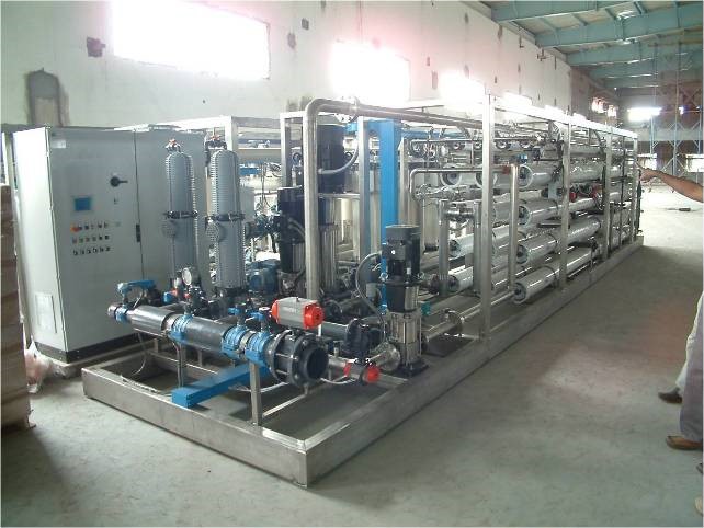
Reverse Osmosis plant
Reverse osmosis (R.O.), distillation and ion exchange are the major desalination processes currently in use. Of these four processes the reverse osmosis is generally the most economical for desalting either brackish water or sea water. R.O. has also become the most widely accepted method for desalting brackish water. Sea water desalinization using R.O. is following a similar pattern of growth spurred by major savings in capital and energy cost, when compared with traditional processes.
Osmosis is a natural process. Pure water naturally flows from a dilute saline solution, through a membrane, into a more concentrate solution. The concentrated solution then becomes diluted with this flow of pure water. Pure water, separated from a salt solution by a semi permeable membrane readily passes through the membrane. The membrane retards the flow of dissolved solids (salts). Water flow across the membrane continues until the pressure created by the osmotic head equals the osmotic pressure of the salt solution. This is called osmotic equilibrium. By applying external pressure greater than the osmotic pressure to the salt solution, the water flow across the membrane can be reversed. By reversing the flow from salt solution to pure water, pure water is removed from the more concentrated salt solution. This is the process of reverse osmosis. Reverse osmosis call for a suitable pre-treatment of raw water in order to prevent damage to the osmotic membrane and to prolong their life.
This offer relates to a plant of reverse osmosis purification, completed by a pre-treatment section. The installation will be automatic, completed by manual cleaning in place station and all the accessories necessary for the operation.
Process description
Firstly, water is entered in the cartridge filtration. The degree of filtration of the cartridge filters is 5 micron, in this way we can remove all the smaller particles that could be formed during chemical conditioning or that are possibly leaked through the multimedia filter. The filters cartridges can be easily substituted, this step is essential for the safety utilization of the reverse osmosis membranes. Special cartridge filters are utilized; they are obtained by the melt blow technology with two effective degree of filtration in series in the same cartridge providing a volume filtration.
Water is now pressurized to the reverse osmosis modules, where nearly all dissolved salts are held back, while pure water is forced through the semi permeable membranes.
The treatment plant described is automatic and controlled by one PLC unit equipped with touch screen interface. The plant is completely automatic. The high recovery obtained by this installation is reached by the utilization of three concentration steps:
- First step: brackish water R.O. membranes fouling resistant; recovery of the first step: circa 75%; work pressure: 15-18bar.
- Second step: high pressure process R.O. membranes; recovery of the second step: circa 60%; work pressure: 20-22bar
- Third step: high pressure process R.O. membranes; recovery of the second step: circa 50-55%; work pressure: 30-32bar
The three concentration steps are disposed in series, with boosters units located between the different steps. This configuration permits to optimize the membrane performance realizing the better flow and pressure profile and at the same time to maximize the energy saving.
The main pressurization pumps are controlled by inverter, the inverter in commanded by the PLC, in this way we can strictly control the process, with the optimization of the membrane surface utilization and the best energy efficiency.
The membrane cleaning system is composed by one unit. The unit is composed by three cleaning loops; every loops is dedicated to a specific membrane array group. Every membrane array group needs different flow rate so, with a specific recirculation loop for every membrane array group we can execute the cleaning procedure in the shorter time optimizing the performance of the cleaning procedure with the minimum chemicals consumption.